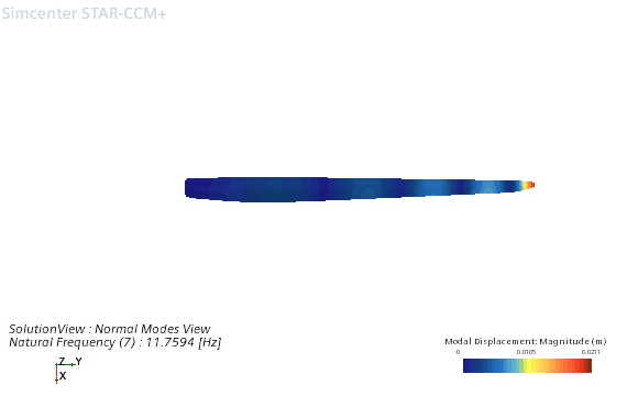
Visualizing the Normal Modes
In Simcenter STAR-CCM+, you can visualize the normal modes solution using a Normal Modes View. The primary use of the Normal Modes View is to apply a normal modes representation to scenes or reports. You can also use the normal modes representation to add annotations to plots.
To create a normal modes solution view:
- Right-click the node and select New Normal Modes View.
- Select the node and set the Result Type.
-
Select the node and set the Mode.
For more information, see Normal Modes View Reference.
-
Create the appropriate visualization tool:
- Scalar or Vector Scene:
- Create a Scalar or Vector scene.
-
Select the node and set Parts as appropriate to display the results.
You can only visualize the normal modes representation when using the following parts as inputs:Part Types Derived Part Types - Part Surfaces
- Regions and Boundaries
- Vector Warps
- Select the node and set the Representation to Normal Modes View.
- Select the node and set Function to
Modal Displacement.The Modal Displacement is currently the only physical result (in addition to the standard metric field functions) available for the normal modes view.
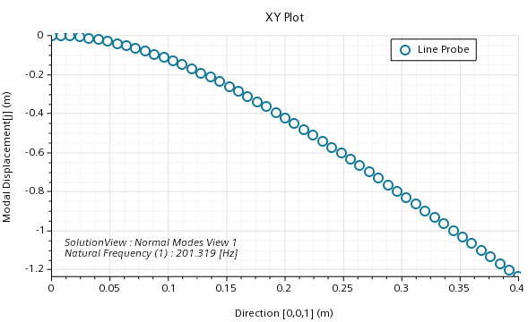
- Plot:
- Create a plot.
- Select the node and select Normal Modes View.
- Select the node and set the appropriate properties.
- Report:
- Create a report.
- Select the node and set the following properties:
Property Value Field Function Modal Displacement Representation Normal Modes View - Run the report.
注 Only specific report and part combinations are currently available for reports
- Scalar or Vector Scene: